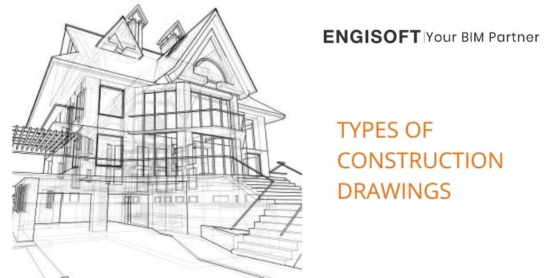
Before beginning the project, it is critical to creating a construction plan. It provides a comprehensive overview of the structure. Keeping this in mind, many different types of construction drawings are now used for this purpose. In addition to presenting technical details in a legible manner, these drawings are required for project clearance. They serve as a guideline for the building process and ensure that building codes are followed.
What Is A Construction Drawing?
It is a graphic representation of what will be constructed, how it will be organized, and its parts, structure, and measurements. Every component of a construction project has a construction drawing that highlights the specifics. The various groups of workers tasked with carrying out or supervising the various tasks that comprise a construction project can benefit from construction drawings, including all of its subtypes.
How Are Construction Drawings Created?
Hand-drawn construction plans are no longer commonly used. Either hand-drawn sketches or computer-aided drafting (CAD) software is used to create them. Additionally, modern Building Information Modeling (BIM) software has made it simple to render and see the virtual construction models in great detail (VCM).
Common Types of Construction Drawings
Architectural Drawings
Architectural drawings are pieces of art that are used in building plans to show the size, depth, and layout of the finished building before construction is started. Architectural drawings serve as a scale blueprint of the building to aid engineers in visualizing the project. Various types of architectural drawings that are frequently used include:
Foundation plan
The foundation plan should not be confused with the ground or basement floor plan. Foundation Plans are drawings used to depict any of the floors of a building that is being built. They aid in visualizing the dimensions, size, shape, height, and configuration of rooms/stairs/landings in relation to one another.
Floor plans
Floor plans are detailed renderings of the room layouts for each floor. It describes the orientation of rooms and components in 2D. Floor plans may or may not be used in commercial or non-commercial building projects, but they must be created as part of the drawing process.
Sectional Drawings
These are drawings that show a sliced section of the framework. It aids in understanding the measurements of various building components in relation to one another, the materials used in their construction, the height, depth, hollowness, and so on.
Elevation Drawings
These architectural drawings provide an aesthetic overview of the building’s various components such as columns, windows, and doorframes. It also aids in comprehending the relative surface, internal markings, and relative height of these various components to one another.
Production Drawings
These Construction Drawings are used to communicate functional information to on-site workers and engineers. It describes the materials, the assembly of various parts, the tools needed, the dimensions, and any other information that is needed during the process. It could also include more information or an infographic on how to meet the requirements.
Electrical drawings
Most residential or commercial construction drawings call for a functional outline of the number of power outlets, light fixtures, fan fixtures, and so on. They also include the wiring pattern and information about the electrical load that it can support. Electrical drawings frequently include the following details:
- Layout of earthing
- The layout of light fixtures
- Generator and other tools
- The layout of the cable tray
- Classifications of hazardous areas
- Lighting security system
HVAC Drawings
Mechanical construction drawings are what these are. They provide details as well as a design framework for a building’s heating and ventilation systems. Central heating/cooling, air conditioning vents, ventilators, and other features are all included in the building plans based on the need and location. Builders incorporate these design constructs into their processes as needed.
Firefighting Drawings
Safety design is critical in today’s construction systems. Firefight Drawings are part of a building’s blueprint drawings that allocate points for fire hoses, fire escapes, water outlets, sandbags, or any other fire safety equipment required by the regulatory body overseeing the project.
FAQ
What are construction drawings?
Construction drawings depict what will be built, how it will be laid out, the components, framework, and dimensions. A construction drawing highlighting the details for each aspect of a construction project is available.
What are architectural construction drawings?
Architectural Construction Drawings are drawings used in building plans to depict the dimensions, depth, and layout of the actual building before construction begins. Architectural drawings serve as blueprints, drawn to scale, to assist engineers in visualizing the project.
How to make construction drawings?
A set of working drawings covering various aspects of the project plan is usually included with construction drawings. Elevation drawings, Floor Plans, Sections, and Detail Drawings are common components of these drawings.

